Global Clean Energy Intelligence Edition
GCES PORTAL
Global Clean Energy Systems Intelligence
How Do 210mm Silicon Wafers Affect Solar Module Performance?
A higher module power rating can make a solar project look simpler on paper: fewer modules may be needed to reach a target DC capacity. Yet the change behind that rating often deserves a closer look. 210mm silicon wafers support larger cells and, depending on how those cells are cut and interconnected, can enable larger-format modules with higher nameplate power. They do not, by themselves, guarantee higher module efficiency or greater energy production per installed kilowatt.
For technical evaluators, the distinction matters. A module built around a 210mm wafer platform may change string current, inverter selection, mounting requirements and handling practices. Its value emerges from the complete design and the conditions at the project site—not from wafer dimensions alone.
What does the 210mm wafer size actually describe?
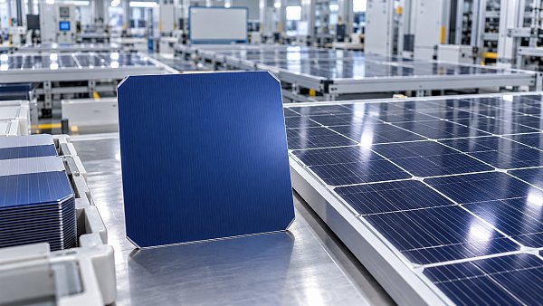
The designation refers to the nominal width of the original silicon wafer, not the dimensions of the finished solar module. Manufacturers process the wafer into a cell and may then divide that cell into smaller pieces before interconnection. A module described as using a 210mm wafer platform can therefore contain half-cut, third-cut or other cell formats, with different circuit layouts and electrical characteristics.
A larger wafer provides more active cell area. If two cells have the same conversion efficiency, the larger cell can generate more power simply because it captures more light. The finished module’s output, however, also depends on the number of cells or cell pieces, the space between them, interconnection losses, glass and encapsulant properties, and the area occupied by the frame.
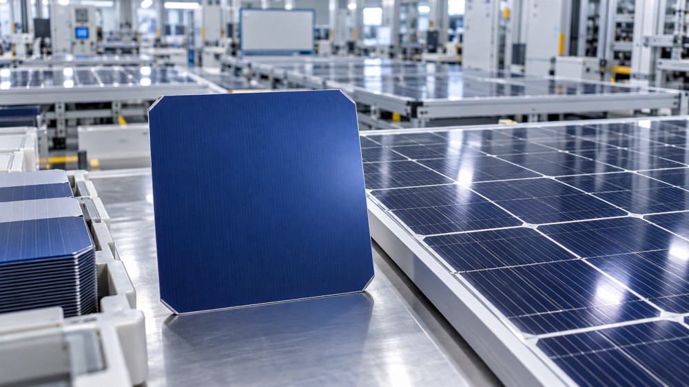
This is why a comparison based only on cell count can be misleading. A count of cut cell pieces is not necessarily equivalent to the same number of full-size wafers. Evaluators should check the manufacturer’s cell dimensions, cutting format, module area and circuit diagram alongside the headline wattage.
Power rating is not the same as efficiency
Module power at standard test conditions, or STC, is measured at an irradiance of 1,000 W/m², a cell temperature of 25°C and a specified reference spectrum. Module efficiency expresses how effectively the module’s total area converts that incident light into electrical power under those conditions.
Consider two hypothetical modules, both rated at 22% efficiency. A 2.5 m² module would be rated at approximately 550 W, while a 3.0 m² module would be rated at approximately 660 W. The larger unit has more nameplate power, but neither produces more STC power per square metre. This example illustrates the area effect; it is not a comparison of specific commercial products.
Efficiency can still differ substantially between products using different wafer formats. Cell technology, passivation, metallization, interconnection and module packaging all matter. A 210mm module using one cell architecture should not be assumed to outperform—or underperform—a smaller-wafer module using another.
Where the larger format can affect system design
Higher power per module can reduce the number of modules, module-level connections and individual handling operations needed for a given DC capacity. Whether those reductions translate into lower installed cost depends on the module’s dimensions and weight, mounting design, labor arrangements and electrical configuration. A larger module may also change the number of modules that fit on a tracker row or within a roof zone, leaving unused space that offsets part of its theoretical advantage.
Current, voltage and inverter compatibility
Large cell area can increase generated current. Manufacturers manage this through cell cutting, parallel circuit paths and other interconnection choices, so a 210mm-based product must be assessed from its actual electrical specifications rather than its wafer label.
Two values deserve particular attention: maximum power current (Imp) and short-circuit current (Isc). Compare them with the inverter’s limits for each maximum power point tracker (MPPT), including its maximum operating input current and maximum permitted short-circuit current. These are different limits and should not be treated as interchangeable.
If string current exceeds the inverter’s operating input capability, the inverter may limit usable current under some conditions, causing avoidable energy loss. Exceeding a manufacturer’s permitted short-circuit current or other connection limit can make the configuration unacceptable. Check the inverter documentation for the relevant limits and how they apply when multiple strings share an MPPT.
Voltage needs a separate review. Calculate the highest expected string open-circuit voltage at the site’s minimum design temperature, using the module’s voltage temperature coefficient and applicable design rules. Also check that operating voltage remains within the inverter’s MPPT range in hot conditions. A high-current module may lead to a different number of modules per string, changing combiner, cable and inverter sizing decisions.
What changes in real-world energy yield?
Installed capacity is only the starting point. Annual energy yield depends on irradiance, temperature, orientation, shading, soiling, electrical losses, availability and degradation. Wafer size influences some design choices, but it does not determine all of these outcomes.
Temperature behavior
Solar module output generally falls as cell temperature rises. Compare the product-specific temperature coefficient of maximum power and use a temperature model appropriate to the site and mounting arrangement. A larger module is not automatically hotter or more temperature-sensitive because it originates from a larger wafer; glass construction, ventilation, mounting height and operating conditions also influence heat dissipation.
For a hot rooftop with limited airflow, the difference between two modules’ temperature coefficients may matter more to modeled yield than a difference in wafer size. Conversely, a ground-mounted installation with good rear ventilation will experience a different thermal profile. Use the same weather data and modeling assumptions when comparing alternatives.
Partial shading and mismatch
Cell cutting and circuit layout can affect how losses develop when part of a module is shaded. Bypass diodes protect groups of cells and can limit the extent of some shading losses, but the outcome depends on which cell groups are shaded, diode arrangement, module orientation and string configuration.
Do not infer shade tolerance from a half-cut or third-cut label alone. Request the internal circuit layout and model the actual shading pattern, particularly where row-to-row shading, parapets, equipment or vegetation are relevant. For bifacial modules, rear-side irradiance, ground reflectance and mounting geometry add another layer to the yield assessment; wafer size alone does not establish a bifacial gain.
Mechanical loading and reliability: evaluate the assembly
A larger module presents a larger surface to wind and snow and can impose different demands on its frame, glass, clamps and support structure. The relevant question is not whether a 210mm-based module is inherently reliable, but whether the specific module and mounting configuration are suitable for the site’s design loads and installation conditions.
Review the manufacturer’s approved clamp positions, mounting rail arrangement, bolt locations where applicable, and permitted static loads. Load ratings must be interpreted with their stated test conditions and safety factors; a test load should not be casually equated with a site design load. The mounting supplier’s approval is equally important, especially where tracker deflection, torsion or unusual support spans are involved.
Cell cracking and interconnection fatigue are also worth examining. Mechanical stress can arise during transport, installation and operation. Glass thickness, frame design, cell processing and interconnection technology all affect the result. Ask for relevant test reports and understand whether testing reflects the proposed mounting arrangement rather than relying on a generic statement about the wafer platform.
For procurement, consider packaging dimensions, lifting arrangements, access routes and safe handling. A module that reduces piece count may still require different crew procedures or equipment on a constrained roof. Those practical details can affect both installation cost and damage risk.
Which standards and evidence should evaluators request?
International standards provide a common testing framework, but certification does not replace project-specific engineering. Confirm the applicable edition, certification scope and product variant, including dimensions, bill of materials and mounting conditions. Relevant documents commonly include:
- IEC 61215 series: design qualification and type approval testing for terrestrial photovoltaic modules.
- IEC 61730 series: module safety qualification, including construction and testing requirements.
- IEC 61701 and IEC 62716: salt mist and ammonia corrosion testing where coastal exposure or agricultural environments make them relevant.
- IEC TS 62804-1: testing for potential-induced degradation in crystalline silicon modules, where applicable to the product and system design.
Standards and local requirements vary by jurisdiction and project. A certificate demonstrates the scope stated in its documentation; it should not be interpreted as proof that every possible installation, climate exposure or lifetime performance outcome has been tested. Review warranty terms separately from qualification results, including degradation assumptions, exclusions, claim procedures and the legal entity responsible for the warranty.
A practical comparison for technical teams
When evaluating a 210mm-wafer module against an alternative, compare complete system designs at the same site and target capacity. The following checks help separate genuine project value from a larger nameplate number:
- Normalize the baseline. Record module efficiency, dimensions, mass, STC power and power per unit of module area. Confirm cell technology and cutting format.
- Build workable strings. Check cold-voltage limits, hot operating voltage, MPPT current limits and the number of strings allowed per input.
- Test the layout. Compare modules per tracker row, roof section or mounting table, including setbacks, access paths and unused space.
- Model energy consistently. Apply the same weather file, soiling, shading and availability assumptions; use product-specific temperature and degradation inputs where supported.
- Review delivered and installed cost. Include freight, mounting hardware, wiring, inverter configuration, labor and any special handling requirements—not just module cost per watt.
- Verify the evidence. Match test reports, certificates, warranties and approved mounting details to the exact product proposed for purchase.
The outcome may differ by application. A utility-scale project with compatible trackers, inverters and logistics may benefit from fewer high-power modules. A constrained commercial roof may place greater value on module dimensions, usable layout and handling flexibility. Neither result follows automatically from wafer size.
In short, 210mm silicon wafers are an enabling platform rather than a performance guarantee. Their effect on a solar module is mediated by cell architecture, circuit design and mechanical construction; their effect on a project depends on how that module fits the electrical system and site. The strongest technical comparison follows the chain from wafer to module, from module to string, and from string to lifetime energy and cost.
Global Energy Questions? Contact GCES Portal
Related News
 Cells & ModulesHow Do 210mm Silicon Wafers Affect Solar Module Performance?Discover how 210mm silicon wafers affect solar module power, efficiency and system design, and learn what to compare before choosing a module.MORE+
 Cells & ModulesHow Do Battery Separators Affect Lithium-Ion Battery Performance?Battery Separators influence lithium-ion battery power, charging, lifespan, and safety. Discover key trade-offs and the evidence you need to make smarter cell selection decisions.MORE+
 Cells & ModulesTCL SunPower Launches Origin Residential Solar Modules With Up to 24.7% EfficiencyTCL SunPower Origin residential solar modules offer 485–505 W and up to 24.7% efficiency. Explore back-contact technology, shading resistance and a 40-year warranty for your roof.MORE+
 Cells & ModulesWhat solar panel hail test ratings mean for real-world protectionSolar Panels hail test ratings explained: learn what lab results reveal, spot hidden risks, and compare protection claims to make smarter buying decisions for your project.MORE+