Global Clean Energy Intelligence Edition
GCES PORTAL
Global Clean Energy Systems Intelligence
How to Select Laminated Busbars for Power Inverters
How to Select Laminated Busbars for Power Inverters
Selecting laminated busbars for power inverters requires more than matching current ratings to a design specification. Stray inductance, thermal performance, insulation, voltage transients, and mechanical integration can all affect switching behavior, efficiency, and long-term reliability. This guide examines the technical criteria that evaluation teams should consider when comparing busbar designs for solar, energy storage, and other power conversion applications, helping them assess trade-offs and specify components suited to the inverter’s operating conditions.
The most useful starting point is the complete commutation loop, not the busbar in isolation. A design that looks attractive on a component drawing can lose its advantage when capacitor connections, power-module terminals, fasteners, and mounting clearances are included. Conversely, the lowest quoted inductance is not necessarily the best choice if it requires insulation compromises or creates a thermal bottleneck.
Start with the inverter’s electrical operating envelope
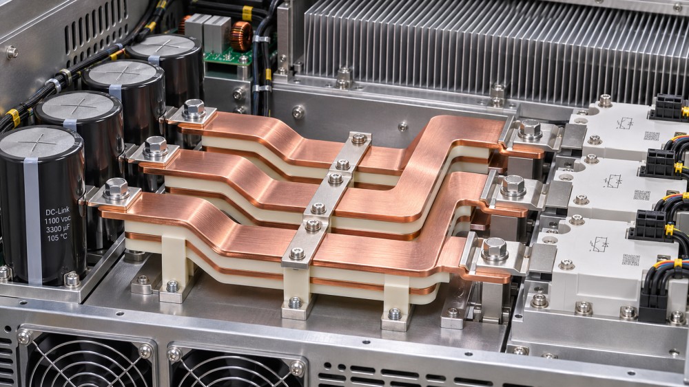
A laminated busbar typically combines flat conductors separated by insulating material in a compact assembly. Closely spaced positive and negative current paths can reduce loop inductance compared with less controlled wiring arrangements. The result depends on the geometry of the entire current path, including where the conductors separate to reach terminals.
Before comparing designs, define the maximum DC-link voltage, normal voltage range, continuous and transient currents, switching characteristics, and expected fault conditions. Include the actual capacitor and semiconductor arrangement. For a bidirectional battery inverter, specify both charge and discharge duty rather than assuming one operating direction represents the full thermal and electrical load.
The operating envelope should also describe altitude, ambient temperature, cooling conditions, humidity, contamination, and expected service life. These inputs are not administrative details: they affect insulation coordination, temperature rise, corrosion risk, and ultimately the allowable design margins.
Evaluate inductance at the switching loop
During switching, parasitic inductance produces a voltage contribution approximately proportional to L × di/dt. That contribution can increase the voltage stress seen by semiconductor devices. A fast-switching silicon carbide design may therefore place different demands on the layout than an inverter with slower switching transitions, even when their nominal current and DC voltage are similar.
Ask how an inductance figure was obtained. A value for the laminated section alone is not directly comparable with a value for the full loop from capacitor through the switching devices and back. The measurement or simulation should identify the terminals, current paths, frequency or test conditions, and included connections. Where possible, compare alternatives using the same boundaries.
Greater conductor overlap and smaller separation can reduce inductance, but thinner insulation may constrain voltage withstand or manufacturing robustness. Terminal geometry can also dominate the result: a compact laminated stack connected through long, separated tabs may not perform as its headline specification suggests.
Low inductance is valuable, but not in isolation. Changing conductor spacing and overlap also changes parasitic capacitance, which can influence high-frequency current paths and electromagnetic compatibility. Assess the busbar alongside gate-drive settings, capacitor placement, shielding, and grounding rather than treating it as a standalone EMI remedy.
Check current capacity against real heat paths
A current rating is meaningful only with its assumptions. Request the permitted temperature rise, ambient temperature, airflow, mounting orientation, conductor configuration, and duty cycle behind the rating. A busbar tested in open air may run hotter inside an inverter enclosure beside capacitors and semiconductor heat sinks.
Conductor cross-section affects resistive loss, but it does not tell the whole story. Ripple current, current crowding around holes and tabs, skin and proximity effects, and uneven current sharing between parallel paths can create localized heating. Electrical joints deserve particular attention: contact resistance can turn a small interface into a persistent hot spot.
For an energy storage inverter, the relevant duty may include repeated high-power charge and discharge periods. A solar inverter may spend long periods near high output under strong irradiation while enclosure temperatures are elevated. Neither application is well represented by a single current value without a time profile and cooling assumptions.
Compare thermal simulations with prototype measurements at conductors, joints, insulating edges, and adjacent components. Confirm that measurement locations capture likely hot spots and that the test reaches a representative thermal condition. If a supplier offers only a generic ampacity figure, treat it as a screening input, not final design evidence.
Match insulation to voltage stress and the installation environment
Insulation selection must account for more than nominal DC voltage. Switching overshoot, transient overvoltages, temperature, humidity, contamination, mechanical damage, and aging all matter. The interlayer dielectric and the exposed edges of the assembly need separate attention; a strong insulating film does not automatically resolve inadequate clearance or creepage at a terminal.
Define the applicable insulation coordination requirements for the complete equipment, including the intended market, pollution conditions, altitude, and expected overvoltage environment. IEC 60664-1 is one relevant reference for insulation coordination in low-voltage equipment, but the applicable product standard and project requirements must also be checked. A busbar supplier’s material data sheet is not, by itself, evidence that the completed inverter complies.
Review dielectric withstand test conditions, acceptance criteria, and whether testing is performed on every unit or on representative samples. Where fast voltage transitions or repetitive stress are relevant, discuss whether additional assessment, such as partial-discharge evaluation, is appropriate for the design and its applicable requirements. Avoid assuming that one successful high-voltage test establishes lifetime insulation performance.
Compare conductor and interface choices in context
Copper and aluminum can both be used in power distribution, but the choice changes the surrounding design. Copper offers high electrical conductivity and is familiar in many inverter assemblies. Aluminum’s lower density can be attractive where weight matters, although its conductivity is lower and its joints require careful treatment of surface condition, compatible hardware, and long-term contact integrity.
Do not compare material prices without accounting for the required conductor dimensions, plating, joint design, assembly process, and qualification work. In a constrained enclosure, the space needed for an equivalent thermal and electrical design may matter more than raw material cost.
Plating and terminal finishes should be evaluated as part of the complete mating interface. Confirm compatibility with capacitor and power-module terminals, the assembly environment, and the specified fastening method. Different metals, moisture, or contamination can complicate corrosion control; the appropriate treatment depends on the actual joint.
Make mechanical integration part of the electrical review
A busbar that is electrically sound on paper can still create field problems if it transfers assembly stress to semiconductor terminals or leaves insufficient access for a calibrated fastening tool. Review tolerances across the entire stack-up: mounting points, terminal hole positions, insulation thickness, capacitor placement, and enclosure features.
Thermal expansion and vibration can place cyclic loads on joints and laminated interfaces. Assess whether the design needs mechanical support or a compliant connection, and check that any flexibility introduced does not undermine loop geometry or insulation spacing. For transportable equipment or installations subject to vibration, qualification conditions should reflect the expected environment rather than a generic laboratory setup.
Also examine the consequences of a short circuit. The busbar and its supports must withstand the relevant thermal and electrodynamic stresses for the prospective fault current and protection clearing time. These values come from the system design; they should not be inferred from the continuous current rating.
Separate supplier claims from usable evidence
Comparing quotations becomes more reliable when all suppliers work from the same interface drawing and operating assumptions. Ask for enough information to understand what is included in the proposed performance, not just a pass-or-fail statement.
- Electrical model: loop boundaries, conductor arrangement, inductance assessment method, and the connections included.
- Thermal basis: current waveform, ambient conditions, cooling assumptions, temperature limits, and predicted or measured hot spots.
- Insulation definition: material system, exposed-edge treatment, required clearances, dielectric test method, and applicable equipment requirements.
- Mechanical interfaces: tolerances, plating, fastener requirements, support points, and permitted terminal loading.
- Production controls: inspection of dimensions and insulation, traceability, change notification, and the distinction between prototype and production processes.
A simulated result, a prototype test, and a qualified production process are different kinds of evidence. The distinction matters when an inverter moves from engineering evaluation to repeat manufacturing. Ask whether the tested design uses the same materials, geometry, tooling assumptions, and assembly interfaces as the part being quoted. If not, identify what must be revalidated.
Lead time and change control also affect the decision. A custom busbar can tie the electrical layout to a particular manufacturing process or material source. Before design freeze, clarify drawing ownership, tooling arrangements, minimum order conditions, and how substitutions will be reviewed. A lower initial price may be less compelling if a later material change requires repeat qualification or disrupts inverter production.
Choose the design that remains credible at system level
The preferred option is the one that meets the switching, thermal, insulation, mechanical, and production requirements with demonstrable margin under the intended duty. It may not be the thinnest assembly, the highest-current catalog part, or the design with the lowest isolated inductance figure.
This system-level view is especially useful across clean energy infrastructure: an inverter’s busbar choice affects the power conversion assembly, while the operating duty is shaped by the solar plant, battery system, charging site, or grid connection around it. GCES follows these interfaces because equipment decisions are more meaningful when evaluated against actual project conditions and lifecycle requirements.
Before approving a design, align the inverter manufacturer and busbar supplier on the operating envelope, loop definition, insulation criteria, joint details, and prototype validation plan. Record unresolved assumptions and the evidence needed to close them. That gives the evaluation team a defensible basis for selection—and reduces the chance that a promising component becomes a late-stage integration problem.
- Last One:No more articles
- Next Article:All-Energy Australia Highlights Record Battery Storage Growth2026-11-03
Global Energy Questions? Contact GCES Portal
Related News
 Inverters & Balance of SystemHow to Select Laminated Busbars for Power InvertersChoose laminated busbars for power inverters with confidence. Explore inductance, thermal performance, insulation, and supplier checks in this practical guide.MORE+
 Inverters & Balance of SystemWhen does solar inverter clipping justify a larger inverter?Solar Inverters: Is clipping worth an upgrade? Learn how recovered energy, electricity prices, export limits, and lifetime costs reveal when a larger inverter pays off.MORE+

